Max Lyons, March 2014
I have been shooting recently with a 96 megapixel panoramic camera. The camera has full manual control over exposure and focus, and shoots in JPEG and raw formats. It features a zoom lens, so that it can capture scenes with a field of view between 50 and 220 degrees, and the images it creates have a panoramic aspect ratio of about 4:1, although this is configurable. At its widest zoom, the lens opens up to f/2.8 aperture, and the images it produces are surprisingly sharp. I have been using it a lot for night photography, and it can shoot exposures of several minutes with no problem. I use a specially designed cable release to trigger the shutter, change exposure and operate the camera's built-in intervalometer functions. The camera is also modular, so that if I decide that I'd like a 200 megapixel model, or a version that shoots standard aspect-ratio images, it is an easy change to make. The best part is that the camera (including battery and memory card) and cable release only cost about $400.
Sounds too good to be true, right? Well, there is a catch. The 96 megapixel “camera” is actually an array of six 16 megapixel cameras. And, there is some assembly required! These six cameras are triggered to shoot at exactly the same moment, with each camera capturing a different portion of the scene. The images produced by these six cameras are assembled into a final high-resolution composite image using my own PTAssembler software, once they have been transferred to the computer. Read on for more details about this “Very Small Array” (VSA) panoramic camera.
I have been shooting panoramic images for about 15 years, stitching together images captured using a single camera. This works very well, but isn't really suitable for all types of scenes. The main problem is dealing with motion. For example, if there is a lot of motion in the scene (e.g. waves rolling on the beach) or objects are moving around (e.g. sports photography), it may be difficult or impossible to stitch the images together seamlessly. Similarly, changing light (e.g. the sun or moon moving in and out of the clouds) is a problem. I also take a lot of photographs at night, and these motion and changing light problems becomes even more pronounced because of the longer exposures necessary to capture each frame. If a car drives through the scene as I'm capturing it, the car's headlights will only appear in one frame...seeming to abruptly appear and then disappear in one portion of the scene in the final composite.
Even without these problems, taking panoramic images at night with a single camera is a time-consuming proposition. For example, if each exposure is 5 minutes, and you want to capture 6 frames, then you'll need 30 minutes. The problem gets worse with more frames and longer exposures. A multi-camera array allows me to shoot panoramic images much more quickly, and shoot more scenes per session.
To be clear, this isn't a new idea. Photographers, hackers and engineers with an interest in photography have been experimenting with multi-camera arrays for quite some time. Some use these arrays to produce 3D images; some uses these arrays for scientific purposes; Google's street-view project is one of the most familiar examples of image capture using a multi-camera array. But, I hadn't seen a lot of examples of photographers using these devices for “pure” photographic reasons, that is, whose main purpose is simply to try to capture artistic or aesthetically pleasing images. I am also interested in software and hardware projects that are able to create “big” results by clever application of modest hardware (e.g. Hadoop), and this fits nicely into that category. A lot of the existing multi-camera arrays I have seen are heavy, large and bulky. Many require tethering to a computer or external power sources to operate. In other words, they really aren't suitable for use outside a studio.

I'm comfortable writing software, but have very limited skills when it comes to electronics/hardware. Anything involving circuit design or components more complicated than a battery and switch is beyond my current abilities. So, one of my main goals in putting together the array was to construct something as simple as possible, using as many cheap/commodity parts from the hardware store and Ebay as possible, and relying on software wherever possible.
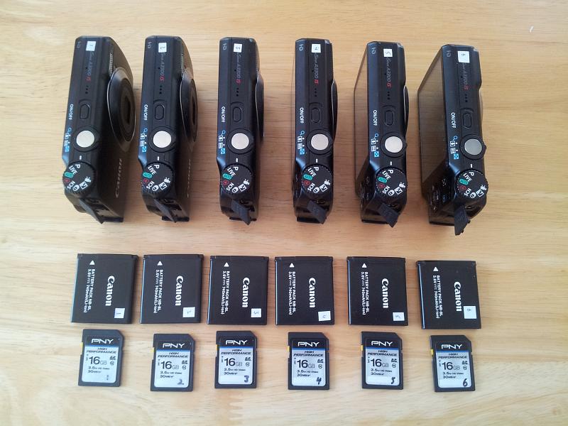
The array is built to incorporate six identical Canon A3300 cameras, a camera model I chose for a few reasons. First, at the time I started the project, the A3300 was one of the most recent cameras supported by the Canon Hack Development Kit (CHDK) project (more on this below). Second, the A3300 is small and light, has a 16 megapixel sensor, a 5x zoom and a good lens (for the price). Third, the A3300 cameras were cheap; I was able to purchase these directly from Canon's refurbished outlet store on sale for about $50 each. I use the same brand and size of memory card in each camera because I wanted to minimize any inconsistencies in write speeds between cameras. I assigned each camera, battery and memory card a number, using stickers and labels. I also changed the volume label for each memory card to its corresponding camera number.
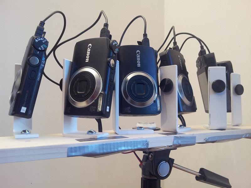
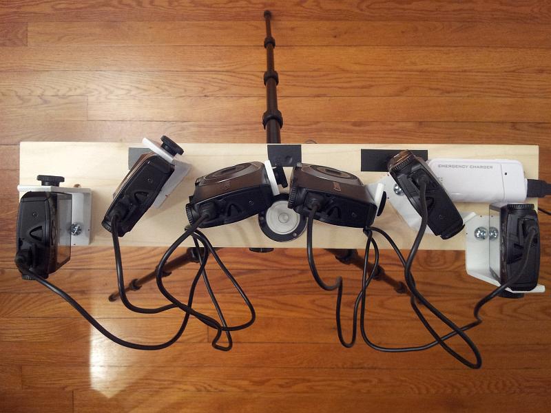
The main platform for the array is a ½ inch thick wooden board with a ¼-20 T-nut inserted in the middle so that it can be screwed onto a standard tripod head. The cameras are mounted onto the board using “L” brackets that I made by taking a hacksaw and drill to a PVC drainpipe/downspout adapter I bought at the local hardware store.


After cutting and drilling, each drainpipe adapter produced four L brackets. I had initially designed a model of an L bracket and intended to fabricate it using 3D printing, but it would have cost 10 times as much as the hacked PVC bracket. The brackets are mounted to the board with a ¼-20 x ¾ inch screw/nut, and the cameras are mounted to the brackets with a ¼-20 x 3/8 inch thumb screw. The ¼-20 thread pattern is the same that is used by most tripods and cameras. Getting the length of the thumb screw is important...too short and it won't hold the camera; too long and it will damage the camera. Given the depth of the tripod socket in the A3300, and the thickness of the L bracket arm, 3/8 inch was just right.
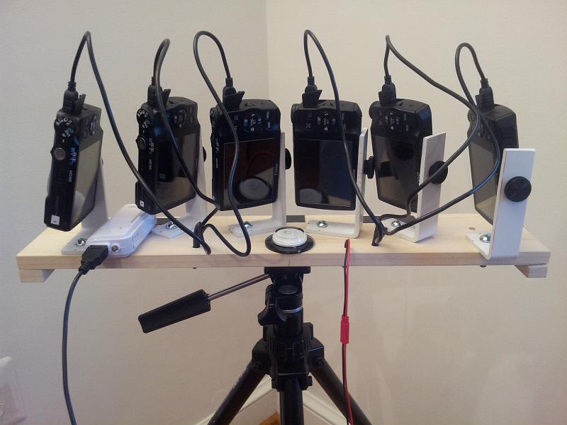
For panoramic images, the ideal camera placement would be to have them all positioned in exactly the same location. Of course, that isn't possible, so I positioned them as close together as possible, offsetting them enough to make sure that one camera wouldn't obstruct the view of another, leaving just enough room between them to allow me to mount the cameras and adjust the brackets and cameras to their appropriate positions. The brackets can be rotated on the board to maintain a small overlap between the images (required by the software used to assemble the images) as the focal length changes. In practice, I shoot most of the time using the cameras' widest focal length, and keep the brackets positioned correctly for this configuration. I made some markings on the board that show me the correct position of the brackets for a range of different focal lengths. I always put the cameras on the board in the same numeric order (camera 1 on the right, and camera 6 on the left); this allows my software to quickly determine the relative position of each image.
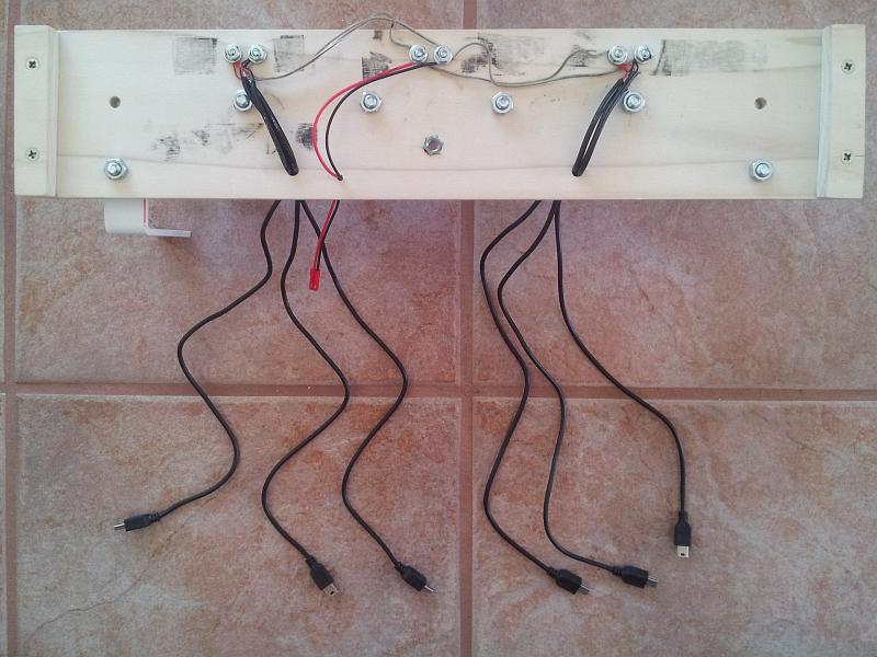
The wiring on the underside of the board allows me to connect a USB cable to each camera. I bought a batch of USB cables with mini USB plugs (the size that fits into the A3300), and chopped off one end of each cable, exposing the wires inside the cables. Each cable has four wires inside, but I only use the red (+5v) and black (ground) wires to connect to the board. The six USB cables are connected in parallel to another cable (with a male JST connector) that can be connected to my “remote controller”. The wiring is fastened with screws and washers. The wires are routed through holes drilled in the board so that the cables are accessible from above; the routing holes are just large enough to allow the cables to be fed through, but provide a snug fit so that the cables do not move on the underside of the board.
The board measures about 18 x 3.5 inches, and weighs a little less than a pound. With all of the cameras, cables and other hardware attached, the total weight is about 3 pounds, about a pound lighter than a Nikon D800 DSLR and Nikon 14-24 lens. Because the array is quite light, it doesn't require a particularly sturdy tripod. I have been using mine with a small Slik Compact XL tripod.
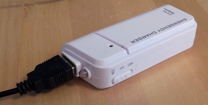
The remote controller is actually a AA-battery powered “emergency charger”, sold for charging cell-phones via a USB port. These are available on Ebay for less than $5. The controller has an on/off slide switch which acts as my shutter trigger (more on this below). I created a cable with a female JST connector on one end and a standard male USB plug on the other, again only connecting the red and black wires. This cable allows me to connect the remote controller to the board, and all the cameras. When the switch on the remote controller is turned on, a 5v signal is sent to each camera's USB port simultaneously.
Of course, the cameras are the most important part of the array. The better the cameras, the better the final result. I needed cameras that could be hacked using CHDK (more about this below) and wanted to find the “sweet-spot” between price and quality. These cameras have relatively small sensors (6.17 x 4.55 mm) and won't win a quality comparison against a digital SLR at the pixel level. However, the small sensors have advantages as well as disadvantages. The main disadvantage is that they tend to produce noisier images with less dynamic range than larger sensor cameras. But, at their base ISO (ISO 80), the images are quite good, certainly good enough to make noise-free prints at large size. Should the dynamic range prove insufficient for a particular scene, it is quite easy to capture a couple of images at different exposures, and created an exposure-blended (or HDR) image. The main advantage is that small sensors produce images with greater depth of field than larger sensors (assuming aperture and subject distance are kept constant). Also, these cameras don't have an adjustable aperture, so they are always shooting “wide open”; At their shortest focal length, the aperture is f/2.8 and the with focus set at the hyperfocal distance (about 6 feet), everything between 4 feet and infinity is in focus. For landscape photography (particularly at night), this is a real plus: fast aperture and huge depth of field.
CHDK. A large part of what makes this possible is the CHDK software. CHDK is a “firmware enhancement” that is loaded into the camera's memory when it turns on, and allows the camera to do all sorts of things that Canon never intended. For example, CHDK adds the following key capabilities to the A3300 (and most other Canon point-n-shoot cameras), all of which are necessary for the camera array to work as I want, and all of which are impossible with Canon's own firmware:
It is the last two of these features that enable me to control the array and trigger all of the cameras simultaneously with a remote controller.
USBShooter. Whenever a camera is turned on, CHDK starts up and, in turn, starts USBShooter, a script that I wrote to implement the exposure, focus, image capture and intervalometer control functions, as well as respond to input from the USB remote. USBShooter is written in LUA, a lightweight scripting language, and runs inside the camera. USBShooter can be configured in a variety of different ways via a menu on the camera. Once USBShooter starts running, it focuses the camera at a specific distance (more on this below), sets the default exposure length (I use 2 seconds as a default for night photography, but this can be changed or set to auto-exposure), sets the number of pictures to take and/or length of time to shoot, and then waits for input from the remote controller.

Once all six cameras are turned on, I can control each camera as normal using its buttons and dials, but this can be time consuming and fiddly since things like changing the exposure length can only be done by navigating menus using small buttons on the back of the cameras. And, pressing the shutter on all six cameras at the same time is impossible. However, I can control all cameras simultaneously using the remote controller. I can't control everything on the cameras this way, but I can control the “important” things:
Remote Controller. By turning the remote controller switch on and off I can send “pulses” to the cameras. USBShooter is configured to monitor the camera's USB port, and respond to short and long pulses (by default, a short pulse is less than 3 seconds, a long pulse is more than 3 seconds). A single short pulse instructs USBShooter to start taking pictures. USBShooter incorporates an intervalometer feature so that it can be configured to shoot multiple frames when triggered, but it can also just shoot one frame in response to a pulse. Each additional short pulse is a signal to change the exposure by half a stop. For example, if the default exposure is 2 seconds, and I send three pulses, then the exposure length will be 4 seconds (the first two pulses change the exposure by one full stop, and the third pulse starts the shooting). If I want to shorten the exposure, then I start the sequence with a long pulse. After an initial long pulse any additional short pulses are interpreted as instructions to shorten the exposure. For example, a long pulse followed by three short pulses will instruct the camera to take a one second exposure.
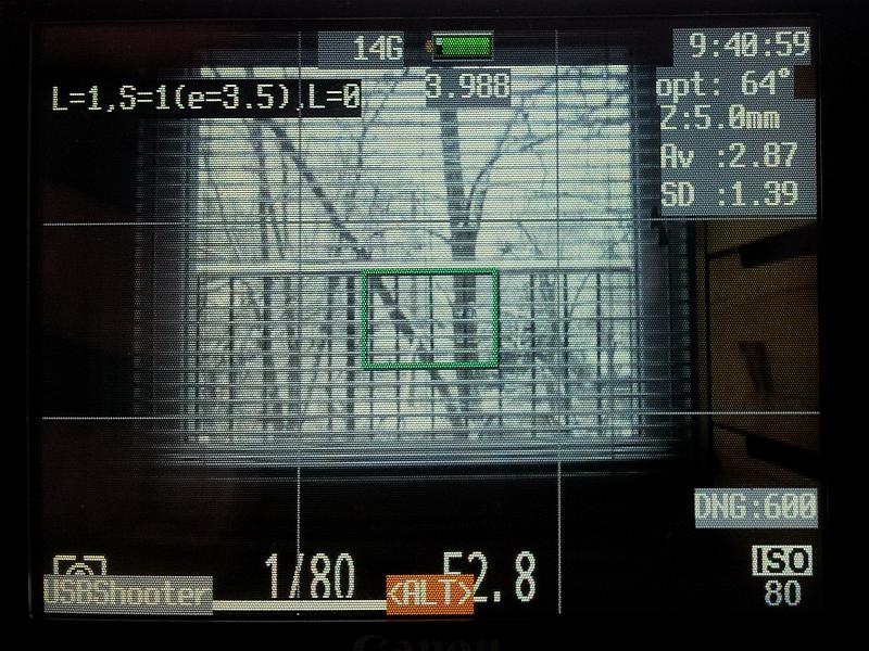
It sounds complicated, but it is quite easy with a little practice. As USBShooter receives pulses from the remote controller, it shows the type and number of pulses it has received, as well as the exposure that will be used in a small window on the upper left corner of the camera's screen, so you can watch the screen while sending pulses to make sure the exposure length is what you want. USBShooter also makes the camera generate different audible tones whenever a short or long pulse is received, so it is possible to confirm that the cameras receive the right instructions just by listening. USBShooter also responds to other pulse combinations to allow me to reset the default exposure and turn off the cameras. In principle, a more complex system similar to Morse code could be implemented to control more and more features, but these are all that I have found necessary for practical photography.
Raw vs JPEG. CHDK gives Canon cameras the ability to capture raw data in raw (DNG) format, which allows for higher quality images and more image-editing flexibility than the camera's default JPEG format. USBShooter always creates DNG files for each picture. However, there is no way to completely turn off the camera's JPEG output, so each time the camera takes a picture, it saves both a JPEG file and a DNG file. I have set it the cameras to record the smallest, most compressed JPEG image possible in order to save time and space. The DNG files are around 24MB in size, while the JPEG images are about 50KB. These JPEG images are still useful for quickly generating previews and rapidly scanning directories of images.
Focusing. Focusing the cameras correctly turned out to be trickier than I had anticipated. I wanted the cameras to focus at their hyperfocal distance (to capture the maximum depth of field from foreground to background possible). In theory, this should be straightforward: Calculate the hyperfocal distance (about 6 feet for these cameras at their shortest focal length), and tell the camera to focus at that distance. In practice, the results differed wildly from camera to camera. Some of the cameras in the array were clearly front-focusing (i.e. focusing at less than 6 feet) so that only the immediate foreground was in focus; others were back-focusing (focusing beyond 6 feet), some significantly enough that nothing was in focus. To solve the problem, I ended taking a lot of test pictures with each camera (at different focal lengths and focus distances) and visually evaluating these test pictures to determine the focus distance that produced the best results at each focal length. (I wrote a different script to automate the image capture/evaluation process). For each camera, I created a small camera-specific file that lists the optimal focus distance for each focal length; each camera has its own file, and this file is used by USBShooter when it instructs the camera to focus.
Once the images are captured, they have to be transferred to a computer, organized and stitched. While one could do all of this manually, I wrote a few programs to automate much of this:
Image Downloader. The Image Downloader program moves pictures from the camera's memory card to the appropriate location on the computer. It organizes the pictures by date and camera number. For example, all of the pictures taken on February 12, 2014 by the six cameras end up in folders like these:
Once I insert a camera's memory card into the computer, the Image Downloader program automatically determines the date and camera number by looking at the memory card's folders and volume label, and copies the images (and log files created by USBShooter) from the card to the appropriate location on the computer. It also analyzes the EXIF data in the images (e.g. shutter speed, capture time, etc.), and writes a small file summarizing that information in each directory.
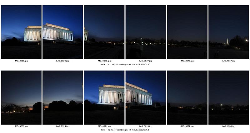
Panorama Analyzer. The Panorama Analyzer program creates a page of “thumbnail previews” of each panoramic image in a directory. It scans all of the images taken in a single session, and determines which images from each camera belong together as part of a panoramic sequence. The program's algorithm is quite intelligent in that it does not rely on the camera's clocks being synchronized, nor does it require that the cameras record the files with any specific numeric order/values. Rather it looks at the relative time offsets in the images' EXIF data in each directory to determine which pictures belong together.
File Mover. The File Mover program copies the raw files from each subdirectory to their common parent directory for processing by the panorama stitching program. The File Mover program is implemented as a Windows Explorer shell-extension so that if I right-click on an image in a directory and invoke the File Mover program, it will locate the corresponding pictures in the other 5 directories that make up the panorama and copy them all to the parent directory where they can be imported as a group into an image editor, stitcher, or other program. It also renames the files slightly assigning a digit representing the camera number to each filename. It does this to avoid the possibility of duplicate/conflicting filenames and to make ordering easier. For example, if all 6 cameras produce files called IMG_0001.DNG, the File Mover script renames them as IM1_0001.DNG, IM2_0001.DNG, IM3_0001.DNG, etc., so that can all be stored in the same directory.
Panorama Stitcher. The Panorama Stitcher program is PTAssembler. This is by far the most complex part of the process, and is a full-featured panoramic stitching program. It combines the images captured by each camera into a seamless panoramic composite image.
CHDK allows the A3300 to record raw images in Adobe's (hopefully to become industry-standard) DNG format. Unlike the JPEG images that the A3300 typically produces, these raw files are not corrected for lens distortion or vignetting, both of which are quite apparent in the raw sensor data. (JPEG images are “corrected” by Canon's software running inside the camera before they are written to the memory card). At first glance, this seems like a problem...the raw images from the camera appear distorted and show significantly darkened corners. The image below illustrates both problems.

However, PTAssembler is able to correct both of these problems while stitching the images into a composite. In fact, it is preferable to do this distortion/vignetting correction at the same time as stitching. This way the images are processed only once rather than twice (i.e. once in the camera for distortion/vignetting correction, and once on the computer for panorama creation). Any processing step has the possibility of introducing artifacts into the image, so it is best to get it all done at once. The image below is a preview generated by PTAssembler that has been corrected for distortion (the vertical lines in the Vietnam Memorial are straight), but not yet corrected for vignetting.
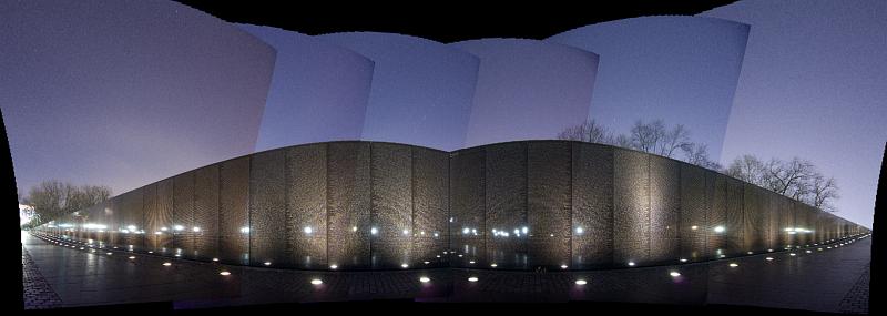
The picture below shows the final result after PTAssembler has corrected for both distortion and vignetting.

There are a few “gotchas” working with a camera array. Just dealing with 6 of everything (6 cameras, 6 batteries, 6 memory cards, 6 chargers, etc.) turns out to be a minor logistical challenge.
All of the cameras need to be configured the same way in order to get predictable behavior. This applies to the Canon camera settings, the CHDK settings and USBShooter settings. All cameras must have the same version of all software, running with the same settings/parameters. In principle, this sounds straightforward. How hard can it be to make the same menu settings? In practice, it took quite a lot of time before I had all the cameras set up correctly. Part of the issue was that I bought refurbished cameras, and they all came with different settings “out of the box”.
The images produced by these cameras are pretty good, but “pixel for pixel” won't challenge a digital SLR. If you want the ultimate “pixel level” image quality, then you may need more expensive cameras in your array. That said, at their base ISO (ISO 80), these cameras produce images that make noise-free prints. And, having 96 megapixels in each image goes a long way to making up for the lower quality cameras.
While is is possible to configure the array to use different focal lengths by changing the orientation of the L brackets and the zoom setting on each camera, this is a little time consuming and isn't something that I typically do “in the field”. In general I stick with a single focal length for each shooting session.
CHDK is quite amazing in the advanced capabilities that it brings to low-end cameras, and it is remarkable that it works as well as it does given that it has been created without any assistance from Canon and relies upon a team of volunteers who have reverse-engineered Canon's “closed-box” hardware. Still, CHDK has some bugs. And, writing a complex script that runs without problems was tricky. USBShooter runs well on all of my A3300 cameras, but it took some tuning (e.g. adding pauses at certain points in USBShooter to allow the Canon software to execute). I'm not sure if it will run correctly on other models without additional tuning. The main issue is that different cameras have different specifications (different processors, different amounts of memory, different capabilities), and so a script that works on one camera, isn't necessarily guaranteed to work on another without some tweaking.

Parallax is probably the biggest issue working with an array like this. Because the cameras are offset from each other by a couple of inches, the images they produce exhibit parallax errors. These errors mean that it is generally impossible to align the images perfectly while stitching. However, because the cameras are fairly close to each other the parallax errors are not large, particularly when the subject matter is more than a few feet away from the camera. Most current stitching/blending software includes logic to hide and/or disguise parallax errors, so in many cases, these errors turn out to be invisible. In some cases, some manual correction may be needed once the composite is created, but my experience is that these corrections are usually quite minor.
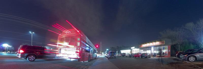
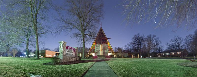
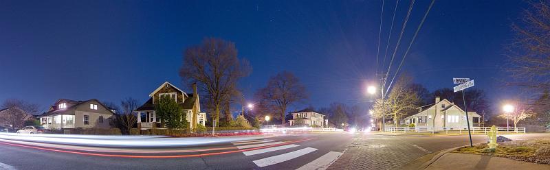
One of the biggest surprises was just how much attention this array receives when I'm shooting in public. I have been approached by the police asking me what I'm doing, people asking nervously “can I help you?”, received more than a few worried glances, and even had one person look at the array and ask loudly “what the hell is that?” from about 30 feet away when he caught sight of me taking the picture below.
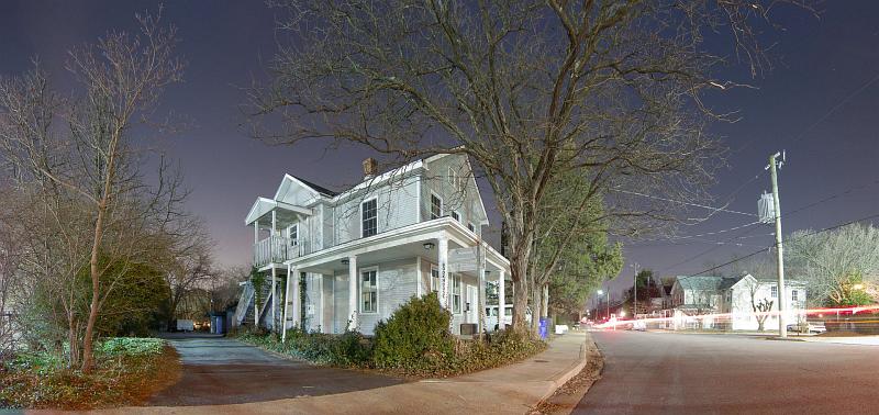
Taking some pictures around the Mall area in Washington DC recently, it seemed that everyone was looking at the array (and me) as they walked by. In general, most people are just curious, but more than a few appeared to suspect that I might be a “terrist” or “evil-doer” up to no good.
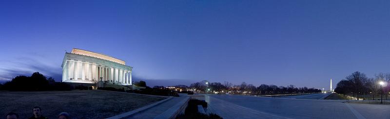
I guess that the wires and cables make the array look scary. And, the fact that I like taking pictures at night may seem even more unusual. Who would want to take pictures at night? Try it in a “non-obvious” location, and there is no question that something suspicious must be going on!

Here is a list of all the parts I used for this array. Prices are approximate. The items came from my local hardware store, McMaster-Carr, Ebay, Canon and Newegg.
This array is more of a working prototype than a final product. There are lots of things that could be improved. For example:

Despite the room for improvement, the multi-camera array works well, and I think that the approach could be easily extended to a much larger array. In fact, I would probably choose to configure a larger array differently, perhaps making a container that would position the cameras in multiple rows (e.g. an array of 5x2 or 20x4 cameras). An array with about 65 cameras could capture up to a gigapixel's worth of data in a single shot. The good news is that the price of point-and-shoot cameras seems to be continually diminishing, perhaps due to the increasing competition from phone-cameras. A gigapixel array at current prices probably wouldn't cost much more than about $4000...not too different from the current price for a high quality full-frame DSLR and lens. Interestingly, DARPA recently announced that it is spending $25 million dollars to do something similar.